3D Print
Contributors

Funding

3D Print Guide
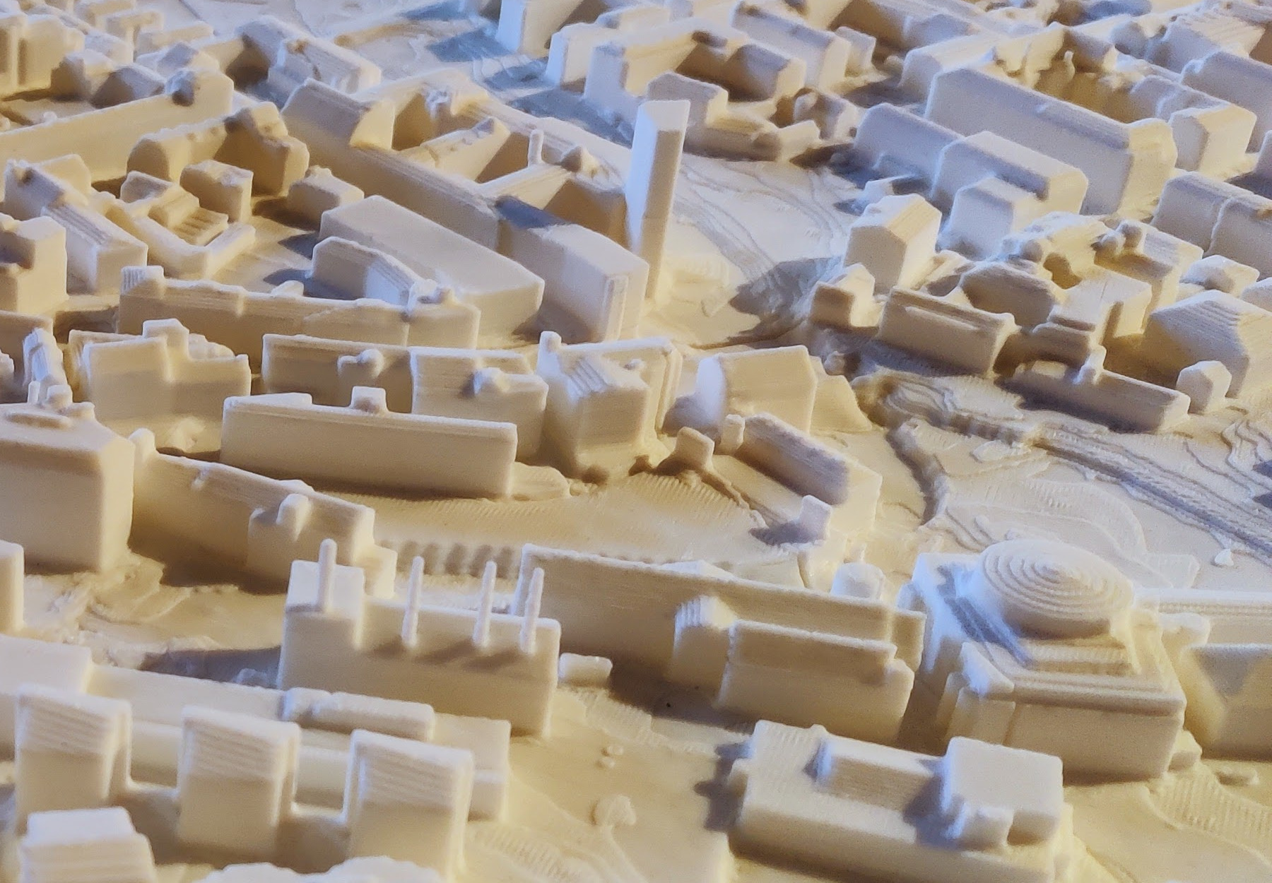
To build a projection-mapped simulation space like SimStad, you need a highly precise physical surface that matches your digital terrain layers. If your target projection area is larger than your 3D printer's build volume, you must process, slice, and register the terrain as a grid of individual interlocking tiles.
This guide details the end-to-end technical pipeline used at Visualiseringscenter C to ingest geospatial data, convert it into a uniform watertight mesh using SideFX Houdini, and physically fabricate the model using optimal filament choices.
+----------------+     +-------------------+     +-----------------+
| 30k+ Georef'd  |     | GeoTIFF / BigTIFF |     | GIS Crop Matrix |
|  FBX Buildings |     |  Terrain Raster   |     |  (Boundaries)   |
+-------+--------+     +---------+---------+     +--------+--------+
        |                        |                        |
        +------------------------+------------------------+
                                 |
                                 v
                      +----------------------+
                      | Houdini Pipeline     |
                      | 1. Alignment & Scale |
                      | 2. VDB Volume Merge  |
                      | 3. Grid Tile Slicing |
                      +----------+-----------+
                                 |
                                 v
                  +------------------------------+
                  | Automated CLI Slicing        |
                  | (PrusaSlicer .STL -> .GCODE) |
                  +--------------+---------------+
                                 |
                                 v
                    +--------------------------+
                    | Physical Fabrication     |
                    | Matte Filament + Coating |
                    +--------------------------+
1. Geospatial Data Ingestion & Pre-processing
Before running automated geometry processing, your input assets must share consistent real-world coordinate structures.
Recommended Tooling
- Procedural Architecture: SideFX Houdini (Core processing pipe)
- Data Prep & Translation: FME, Blender, QGIS, or Autodesk-based GIS tools
- Slicing Automation: PrusaSlicer (Command Line Interface)
Step 1: Geometry & Building Import
Import your building datasets into Houdini. When handling large municipal environments (often 30,000+ distinct FBX models), ensure that your processing nodes preserve the global georeferencing attributes. Verify that all external structural files match the same target coordinate system projection before execution to avoid positional drifting.
Step 2: Terrain Data Extraction
Incorporate high-resolution altitude rasters into your layout. While GeoTIFF/BigTIFF altitude rasters are preferred, the pipeline can flexibly ingest alternative 3D spatial data formats.
- Read the georeferenced raster metadata and extract the individual pixel elevation data.
- Convert the raster array directly into a heightfield or a 3D polygon mesh layer.
- Map the horizontal pixel measurements directly to physical dimensions and set the origin matching your structural coordinates.
Step 3: Boundary Clipping
To isolate your processing window, define an extraction polygon inside your GIS or QGIS layout. Import this vector shape into Houdini and construct a boolean mask to discard any geometry sitting outside your designated municipal boundaries.
Step 4: Physical Scaling
Scale your entire georeferenced dataset down to your real-world target footprint measured in millimeters. Your X and Y axis configurations must scale down uniformly to maintain geographic truth, but the vertical Z axis should remain isolated. This allows you to scale terrain height independently to emphasize subtle ridge features or steep urban elevation if your deployment space requires it.
2. Procedural Mesh Processing in Houdini
Standard architectural structures contain non-manifold geometry, interior walls, and self-intersections that break 3D printers. We resolve this by converting the entire scene into an implicit volume before generating our final printing mesh.
Step 1: Volumization & Extrusion
Extrude the edges of your raw terrain mesh straight down along the negative $Z$ axis to give the canvas a robust, structural base layer, and ensure all building geometries are structurally integrated into this base layout.
Step 2: Implicit VDB Volume Conversion
Convert your combined buildings and extruded terrain meshes into an implicit volume representation (VDB). Perform a boolean union on the volumes to fuse every building, bridge, and landscape element into a single solid layer. This step eliminates intersecting internal polygons and merges floating features.
Step 3: Mesh Reconstruction
Convert your uniform VDB volume block back into a standard polygon mesh surface. This operation yields a homogenous topology across your models and applies a subtle smoothing factor to the sharp geometric gaps where structures meet the terrain.
Step 4: Watertight Mesh Verification
Verify that your reconstructed mesh output is structurally sound. The final file must be completely closed, hollow-free, manifold, and clear of intersecting faces before proceeding to the slicing stage.
3. Grid Tiling and Piece Registration
   [ Tile Grid Matrix ]
+---------+---------+---------+
|  01_03  |  02_03  |  03_03  |
+---------+---------+---------+
|  01_02  |  02_02  |  03_02  |
+---------+---------+---------+
|  01_01  |  02_01  |  03_01  |  <-- Extruded ID text on bottom
+---------+---------+---------+      (e.g., "tile_03_01")
Grid Matrix Generation
Project a clipping grid matrix over your total mesh footprint. You can opt for fixed dimensions tailored directly to your build plates (such as a standard 200x200mm envelope) or use a dynamic variable split based on the total space.
Tile Slicing & Edge Retention
Isolate and clip each coordinate square out of the global mesh using your grid values. Every extracted tile segment must form its own independent watertight block. Ensure that your boundary faces drop down perfectly vertically along the grid boundaries to maintain tight, razor-sharp edge seams when the pieces are assembled side by side.
Bottom Plate Identification Tags
To make assembly straightforward, assign a coordinate identification string to every piece based on its grid coordinates (X, Y). Procedurally extrude this text block inside the bottom surface of the tile model. Sinking the alphanumeric tag into the print base guarantees the identification marking remains permanently readable without distorting the layout alignment or creating structural instability on the display bed.
Model Preparation & Automated Export
For each grid element, reset the local boundary translation relative to the origin coordinate (0,0,0) and verify normal directions across all faces. Run a final mesh safety sweep to clean up non-manifold artifacts or holes.
You can configure an automated file writer loop within Houdini to batch export every processed block out as an individual asset, employing a systematic naming format: tile_XX_YY.stl
4. Automated G-Code Compilation
To speed up production pipelines across hundreds of individual tiles, use the command-line interface (CLI) engine built into PrusaSlicer rather than processing files manually through a graphic interface.
You can write a simple shell or batch script to loop through your exported .stl repository, processing individual modules against your machine profiles to create .gcode outputs automatically:
# Example bash sweep processing directory files through PrusaSlicer CLI
for file in ./export/*.stl; do
  prusa-slicer-console.exe --slice --layer-height 0.2 --load config.ini "$file"
done
5. Material Selection
Always use a matte white filament for the structural prints. Standard gloss or semi-gloss plastics generate specular hot spots under bright projector lenses, scattering light reflections across the model and washing out neighboring visualization layers.
Optional treatment

We tested four distinct surface treatments under the projectors:
- Surface A (Base filament): Raw print using our base matte white filament. This is what SimStad uses today.
- Surface B (Clas Ohlson filament): Raw print using a different white filament.
- Surface C (Base + Coating): Our base filament treated with one coat of sandable spray filler and one coat of flat white paint.
- Surface D (Clas Ohlson + Coating): The Clas Ohlson filament treated with the identical spray filler and paint combination.
Leaving the filament untreated results in a noticeably blurry projection. Applying one layer of sandable spray filler followed by a uniform layer of flat white paint bridges the layer gaps. This post-processing step yields sharper edges and better contrast.
Assembly tips
- Sanding: Expect to perform light sanding and scrape away excess plastic or support strings along the edges of your blocks after printing to ensure a flush fit.
- Fixture: Build a rigid border frame or mechanical channel enclosure directly around your assembled tile matrix. This structure locks the individual prints together tightly, preventing shifting or drift over long operational cycles.